In this research study, three case studies were simulated to understand the transient and dynamic performances of the plant model.
Case Study 1 - Comparison between fault simulated at different locations, Busbar 10 and Busbar 8.
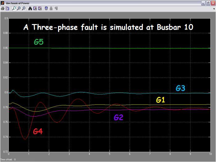
With Area 1 exporting 400MW to Area 2, the parameters using the load flow analysis were programmed into the system model in the MATLAB workspace. The followings show the waveforms of the various control parameters of the plant when a three-phase fault is simulated at Busbar 10 and Busbar 8.
(I) Results:
Responses of Mechnical Power Output (parameter showing the most significant differences)

(II) Discussions: